Programming: Moiré Patterns
In August 2011, Eric Schmidt, the chairman of Google, claimed that the UK is "throwing away [her] great computing heritage" (for similar arguments, see also The Guardian, January 2012; The Telegraph, December 2011). Because students are not taught computer programming, or about computer hardware, in schools there will not be sufficient people with the skills to become the hardware and software designers, developers and programmers of the future.
This point was also made very strongly to me recently when I spent a day shadowing secondary DT teachers. The ICT teacher spoke most emphatically about the need for programming to be taught, and for students to realise that programming skills are very marketable.
A Google search on the skills that programmers need led me to this article: "You Don't Need Math Skills To Be A Good Developer But You Do Need Them To Be A Great One". The writer claims that "I've come to the realization that you need a decent level of math skill if you want to do cool and interesting things with computers."
Programming involves considerable mathematical skill and is also a useful context for mathematical progression.
So why don't we use programming in maths to help get that point across - and at the same time provide a context for students to use their maths skills creatively? I have long thought that Logo is seriously under-used as a mathematical resource for teaching problem-solving, geometrical thinking, and much more.
As an example, these Moiré patterns require only the simplest programming skills, and almost anyone should be able to create these designs and others like them.
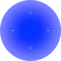
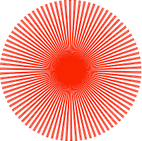
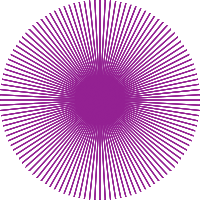
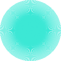
These graphics were all created in Logo using only straight lines. The patterns you see are caused by the Moiré effect. This is a form of interference pattern, which occurs when sets of lines are overlaid at a slight angle, or when a grid has slightly different mesh sizes, or more precisely when two regularly repeating patterns with slightly different periods are superimposed (watch this YouTube video for examples created with ordinary household objects, to the sound of a Mozart piano sonata).
Moiré effects aren't always desirable. They can occur on monitors and TV screens, when we see a wavy pattern superimposed over the image we're supposed to see; they can also occur when a photo is scanned into a computer from a printed page, particularly from newspapers. Modern software and scanners are programmed to eliminate unwanted Moiré effects.
It is claimed that the most striking patterns occur when there is a simple relationship between the frequencies of the repeats. All the graphics shown in this article were created by trial and error, as I explored the potential of Logo for creating these patterns. However since Logo procedures which use variables provide an easy to use tool for exploring which combinations of values lead to interesting patterns it would be straight-forward to move from trial and error to more purposeful investigation.
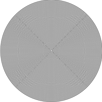
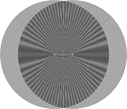
The classic Moiré pattern is created by overlaying sets of concentric circles. The image on the right is simply a set of 50 concentric circles drawn in Logo - the patterning you can see is caused by the Moiré effect. The lower image was created by superimposing two identical sets of 50 concentric circles with the centre of the second set displaced horizontally from the first set. (You can see further examples like this in this YouTube video.)
Designers use Moiré patterns to create specific effects (look here - or watch these YouTube videos: moire, Mr Spocks Sensor Moire Pattern, and many others).
So let's get our students using maths creatively through programming, and at the same time bring maths and DT together.
The coloured images above are all created from radial lines. The interference effects are created from the small angles between lines and in some cases by also varying the lengths of the lines (see the table below for details - there are links to text files of Logo programs* you can try out and adapt). These are all very straight-forward to create from scratch using just a few simple commands. The concentric circles were drawn with a slightly more complex program (requiring the use of variables and procedures).
Students could be provided with these programs to execute, then encouraged to change them to create their own Moiré designs.
| No. radial lines | Length of lines | Angle between lines | |
|---|---|---|---|
| Blue | 360 | All 100% | 1 degree |
| Red | 90 | All 100% | Alternately 3 degrees and 1 degree |
| Purple | 365 | Alternately 100%, 25% and 10% | 7 degrees |
| Green | 800 | Alternately 100%, 25% and 15% | Alternately 7, 5 and 2 degrees |
| Another red pattern (not illustrated) | 180 | All 100% | 2 degrees |
For the images above, 100% meant 100 pixels. Experiment with different lengths of lines and with different angles between them. What difference does it make how many lines you have, or whether you vary the lengths of the lines or the angles?
I found that changing an angle by just 1 degree could make a major difference to how the pattern looked, and sometimes it made the difference between there being a pattern and just a collection of lines. Why do you think I experimented with an angle of 7 degrees? (It wasn't just a random choice).
You can introduce much more variation in the lengths of the lines and/or the angles by using multipliers which can vary, eg. sin x can be used to get a length of line which is between 0 and 100% of your initial length. To do this, you will need to know how to use variables - see this NRICH tutorial.
* I used ACSLogo for the Mac for my procedures.
Depending on which version of Logo you're using, you may need to use American spellings, so 'color' instead of 'colour'. You may also find that some of the colour numbers don't work - in which case experiment with small numbers and see what you get.
