|
Before we experiment with circuits we need to decide how to record what happens when we change the switches in the circuit from 0 to 1 or from 1 to 0. We use small letters p and q to represent the switches. These switches also represent statements that are true or false. A true statement has truth value 1 and a false statement has truth value 0. In circuit diagrams each switch is either 'on' (representing the number 1 or a true statement) or 'off' (representing the number 0 or a false statement). Combinations of switches called logical gates represent the logical connectives. |
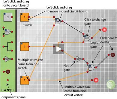
| Fig. 1 gives a summary of the information you need to build your own circuits. |
Fig. 1
|
| First, connect a switch to a lamp as in Fig. 2 and click on the switch several times to change it from 1 to 0 and back to 1. Observe that the light goes on when the switch registers 1 and the light goes off when the switch registers 0. |
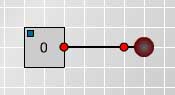
Fig. 2
|
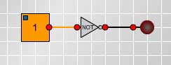
Fig. 3
|
Now put a NOT gate into the circuit between the switch and the lamp, as shown in Fig. 3, and observe what happens when you change the switch from 1 to 0. |
|
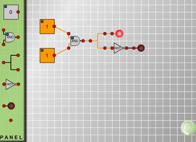
| Make and test the circuit shown in Fig. 4 and fill in the truth table replacing question marks by 1 if the light goes on and zero if the light does not go on. |
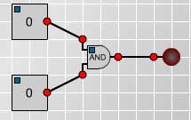
Fig. 4
|
|
| Given any two statementsp, q then p or q, (written p Úq)is given in the truth table on the right. Make the circuit shown in Fig. 5 and replace the question marks by 1's and 0's according to whether the lamp lights up or not. | 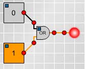 Fig. 5 Fig. 5 |
|
|