Introduction
If you want a very simple introduction to truth tables you
might like to start with
Truth Tables and Electronic Circuits but this article also
provides an introduction to the subject and does not assume any
prior knowledge of truth tables or circuits.
In this article you will find explanations of circuits
and how they correspond to the logical language we use
to discuss mathematics. You will be challenged to
summarise the workings of the circuits by filling in
blanks in the corresponding truth tables. To check your
answers you can then switch to
another version of this article which has all the
truth tables complete.
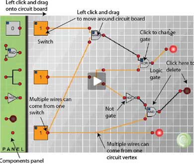
This diagram gives a summary of the information you
will need to build your own circuits.
|
 |
This is the first of a series of articles on mathematical logic which
will show that truth tables, set theory, Boolean algebra and electronic
circuits are essentially equivalent; that is, theorems that can be
proved in one system have their counterparts in the other systems.
In subsequent articles we shall see how Boolean algebra is used in
designing electronic circuits. In this article we begin to explore
the links between electronic circuits and mathematical logic.
Although logic does not model language perfectly it does form a
useful system that, in practice, is the basis of most of the
communication of mathematical ideas between working mathematicians.
Logical conventions are used to overcome the ambiguities and
inadequacies of language. The philosophical aspects of the subject
are rather more subtle and complicated and we shall not dwell on
them.
A proposition is a statement that has exactly one of the
truth values 'true' or 'false'. A propositional function is
a sentence involving variables, for example "She is the Queen of
England" and "x is greater than 7". These functions become
propositions when meanings are substituted for the variables
('she' and 'x' in the above examples).
Before we go on to experiment with circuits we need a notation
to record and summarize the combinations of propositions used in
logical arguments and also the combinations of switches used in
circuits.
We use small letters
to represent propositions. If
the proposition
is true it is said to have the truth value 1
(or sometimes T) and if false the truth value 0 (or F). Propositional
logic is concerned with compound propositions formed from given
propositions by means of the connectives 'not', 'and', 'or',
'if ... then' and combinations of these connectives, for example
'if and only if'.
In circuit diagrams each switch is either 'on' (representing the
number 1) or 'off' (representing the number 0). Combinations of
switches called logical gates represent the logical
connectives.
Logical arguments are a combination of propositions, and circuits
are a combination of switches that control the flow of current.
Modern computers not only store data in the form of '0's and '1's,
on which they perform arithmetic, but perform many highly
complex tasks that we have come to take for granted. Studying the
relation between truth tables and circuits will help us to
understand a little of the underlying principles behind the design
and programming of computers.
Negation
Now it is time to use
Circuit Maker
to make some of your own
circuits and find out how the logic gates work.
|
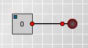
First, connect a switch to a lamp
as in Fig. 1 and click on the
switch several
times to change it from 1 to 0 and
back to 1. Observe that the light
goes on when the switch registers
1 and the light goes off when the
switch registers 0.
|
Fig. 1
|
|
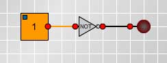
Fig. 2
|
Now put a NOT gate into the
circuit between the switch and
the lamp, as shown in Fig. 2, and
observe what happens when you
change the switch from 1 to 0.
|
Given a proposition
, the negation not-
, written
,
is the proposition demonstrated by this circuit and defined by the
following truth table.
Conjunction
The logical connective 'and' is used to make a compound proposition
from two component propositions. For example if we speak the truth
when we say "Today is Friday and it is raining" then both of the
component propositions are true. If either or both are false
then the compound proposition is false.
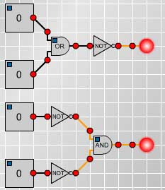
|
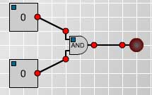
Make and test the circuit
shown in Fig 3. and fill in
the truth table replacing
the question marks with
1's to record when the lamp
lights up and 0's to record
when the lamp goes off.
|
Fig. 3
|
|
If you want to check your work then you can click
here to get the article with all the blanks filled in.
Disjunction
In everyday language we often use 'or' inclusively as in Ïf you want to buy
cereals or soft drinks go to aisle 7 in the supermarket" when we expect people
who want to buy both cereals and soft drinks to go to that aisle as well as
people wanting to buy just one of them. On other occasions we use 'or'
exclusively to offer two alternatives expecting the listener to choose
just one of them as in "Do you want steak for dinner or chicken?". The meaning
is usually clear from the context but to avoid any ambiguity in mathematics
the logical connective 'or' is always used inclusively and never exclusively.
Given any two propositions
and
the disjunction
or
,
(written
)is given in the following truth table.
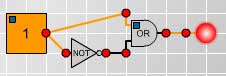
|
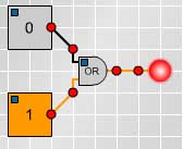
Fig.4
|
Make the circuit shown
in Fig 4. and fill in
the blanks in the truth
table replacing the
question marks with 1's
and 0's..
|
|
Again you can check your work by clicking
here.
|
Fig. 5
|
|
|
|
Again you can check your work by clicking
here.
|
|
XOR, NAND, NOR and XNOR Next we investigate some of the other logical gates used
in circuitry. Then we shall discuss other important logical connectives
such as 'implies', often expressed as 'if... then' as in
" if I go to the shops then I'll buy you some ice-cream".
After that we shall be able to relate the circuits to the
language of logical arguments and also see how circuits can be built to
perform simple operations such as addition.
Now experiment with the circuits for XOR, NAND, NOR and XNOR and complete
the following truth table replacing the question marks with 1's and 0's.
|
|
Comparing these tables to what we have already discovered we see that p NOR q
means 'not(p or q)', that is
, and it is also equivalent to
.
Also p NAND q means 'not(p and q)', that is
,
and it is also equivalent to
.
You can check the truth tables for XOR, NAND, NOR and XNOR by
clicking
here.
Implication Thinking about what we mean by 'if p then q' we see that this rules out the
possibility that p is true and q is false. If I make the promise " if I go to
the shops then I'll buy you some ice-cream" but I go to the shop and do not
buy the ice-cream then I have broken my promise. So, denoting 'if p then q'
by
, the truth table for 'if p then q' must include the line:
As the following example shows true conclusions can be proved by valid
arguments from false premises and so we should expect 'false
true'
to be true.
We shall prove the proposition '2=1
2=2'. Of course 2=2 is true
(by definition) but the following argument proves this as a consequence of a
false hypothesis.
By the symmetry of equality if 2=1 then 1=2. By the transitivity of equality
it follows that, having shown 2=1 and 1 = 2, then 2 = 2.
This establishes a second line in the truth table for implication.
There might still be some doubt in the reader's mind about why the definition
of 'false' implies 'true' is 'true'. It could not be false because then we
would have
logically the same as
which is
not the case. Consider for example
which is true whereas
is false, so we have no choice but to make this
definition for
. Also 'if x then x' is true whether x is true or false so we must have the
complete truth table as follows.
It is convenient to have a single connective which combines
and
. This connective is the bi-conditional
'p if and only if q' (written
)and defined by
the truth table:
We observe that in the truth table for
this compound
proposition is true precisely in those circumstances in which p and q have
the same truth values and this is given by the logic gate p XNOR q. Also
observe that the logic gate p XOR q is equivalent to
.
Note that p XOR q is 'the exclusive or', true when
either p is true or when q is true but not when they are both true. In
everyday language we often use the exclusive or, as in "do you want steak or
chicken for dinner?", but to the mathematician who, by convention, uses only
the inclusive or, the logical answer is " yes" if he wants meat for dinner
and "no" if he does not want meat.
Tautologies If the truth value of a compound proposition is always true for all possible
combinations of truth values of the given propositions, then the compound
proposition is called a tautology. The following truth table and circuit show
that
is a tautology. This is called the Law of the
Excluded Middle because either
is true or
is true and there is
no third alternative.
The Sheffer stroke
The five connectives
can be
defined by one symbol called the Sheffer stroke which was devised by
H.M.Sheffer in 1913. At the time it was simply a piece of pure mathematics,
but later it has had applications in designing electronic circuits from
assemblies of a single component, the NAND gate. We have already seen that
p NAND q is equivalent to 'not p or not q' or, equivalently, 'not (p and q)'
and that it has the following truth table.
|
|
The negation
is equivalent to p NAND p.
The disjunction
is equivalent to
.
Can you make up three circuits, using only the NAND gate, that are equivalent
to the conjunction
, to the conditional
and to the
bi-conditional
?
If you have worked through this article you should now be able to
solve the problems
Simple Counting Machine,
Adding Machine and
Circular Circuitry and not just by trial and error, and you
should be able to explain the circuits.