Copyright © University of Cambridge. All rights reserved.
'AC/DC Circuits' printed from https://nrich.maths.org/
Show menu
DC circuits
Ohm's Law
Ohm's law forms the basis for all DC electrical circuit analysis. It was first suggested by Georg Simon Ohm in 1826 that the current flowing in a uniform conducting wire is directly proportional to the potential difference between its ends. The constant of proportionality relating V and I is known as the resistance R. The unit of resistance is the ohm ($\Omega$).
$V = I R$,
where
$R = \dfrac{\rho L}{A}$,
$\rho$ is the resistivity of the material,
$A$ is the cross-sectional area of the component,
$L$ is the length of the component.
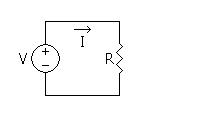
In the simple circuit shown, a battery (or source) delivers current to a resistor. Arrows are used to indicate the sense of the voltage and the direction of the current. Although electrical current is actually the flow of negatively charged electrons, by convention, current is said to flow from high to low potential, as though it were composed of positive charges.
Non Ohmic Devices
Many electrical devices have I-V characteristics that vary in a non linear fashion. Such devices are termed non-linear and do not obey Ohm's law. Examples include filament lamps, diodes and thermistors. The resistance of a non ohmic device may vary with time.
Electrical resistance is a consequence of electrons colliding with ions and losing mechanical energy.
For the case of the filament bulb, an increasing voltage causes the temperature of the filament to rise and as a result the ions begin to vibrate with greater amplitude. This leads to a higher frequency of collisions between electrons and ions; the resistance of the component has hence increased.
A thermistor is a resistor whose resistance varies with temperature. There are two possibilities:
Negative Temperature Coefficient Thermistor: A resistor whose resistance decays with increasing temperature.
Positive Temperature Coefficient Thermistor: A resistor whose resistance increases with increasing temperature.
NTC thermistors are typically constructed from semi-conductor materials. As voltage increases the temperature of the semi-conductor rises, energy becomes available to liberate electrons from their atoms, the charge carrier density and hence the current increases in a non-linear fashion with voltage.
Electrical Power
$P = IV = I^2 R = \frac{V^2}{R}$
Electrical power is the rate at which electrical energy is transferred. Its units are joules per second, or watts.
Resistors connected in series:
Resistors connected in series will have a common current passing through them. The voltage drop across each resistor may be different but all such voltages will sum to the voltage of the supply.
$V_{total} = V_1 + V_2 + ... +V_n$
$I R_{total} = I R_1 + I R_2 + ... +I R_n$
$R_{total} = R_1 + R_2 + ... +R_n$
Resistors connected in parallel:
Resistors connected in parallel will have a common voltage across them but may have a different current through them.
$I_{total} = I_1 + I_2 +... +I_n$
$I=\frac{V}{R}$
$\frac{V}{R_{total}} = \frac{V}{R_1} + \frac{V}{R_2} +... +\frac{V}{R_n} $
$\frac{1}{R_{total}} = \frac{1}{R_1} + \frac{1}{R_2} +... +\frac{1}{R_n}$
Kirchhoff's Voltage Law:
Kirchoff's voltage law is a statement of energy conservation; it states that around any closed loop the sum of the EMFs is equal to the sum of the voltage drops. If we define voltage drops as negative and EMFs as positive, then around any closed loop the sum of the voltages equals zero.
Kirchhoff's Current Law:
Kirchhoff's current law states that the sum of the currents into a node equals the sum of the currents leaving the node. This is a consequence of the fact that charges do not accumulate at nodes. If we define inflows as positive and outflows as negative, then we can say that the sum of the currents into a node is equal to zero.
Mesh/Loop current Analysis
Mesh/Loop current analysis are the application of Kirchhoff's voltage law to solve for unknown currents. In mesh current analysis we assign unknown currents to each element in the circuit. We then apply current conservation at each node. In Loop current analysis we assign unknown currents to each loop, the total current passing through a component is therefore the vector sum of the loop currents through this element. The number of independent equations and unknown will be equal to the number of independent loops.
Question:
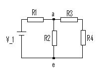
Using Kirchhoff's laws, find the current flowing through each of the components in the diagram below.
Solution:
$\sum_{node\ a} I = I_1 - I_2 - I_3 = 0$
$\sum_{loop\ 1} voltages =V_1 - I_1R_1- I_2R_2 = 0 $
$\sum_{loop\ 2} voltages = I_2R_2- I_3(R_3 + R_4) = 0 $
We therefore have 3 independent equations and 3 unknowns.
Using equation 1 we can eliminate $I_1$ from equation 2
$I_1 = I_2 + I_3$
Equation 2 then becomes: $V_1 - I_3R_1 - I_2(R_1+R_2) = 0$
If we now solve this equation simultaneously with equation 3 we find that:
$I_1 = \dfrac{(R_2+R_3+R_4)V_1}{s}$
$I_2 = \dfrac{(R_3+R_4)V_1}{s} $
$I_3 = \dfrac{R_2V_1}{s}$
where $s=R_1R_2+(R_1+R_2)(R_3+R_4)$
AC Circuits
Most electric and magnetic devices use alternating or fluctuating currents. The two main reasons for this are concerned with power transmission and information processing. Firstly, an alternating electric power may be made available at almost any desired voltage and current level by the use of a transformer. Secondly, fluctuating currents serve a great purpose in information transmission. For example, a microphone will convert the spoken word into a current which has frequency equal to that of the speech. We are hence able to convert physical information into electrical data which we may then process. It is often useful to consider an alternating voltage or current as a sinusoid. In fact, this may not always be the case; the current through a microphone will often take some other form. However, it is true that we may represent any periodic function as a infinite series of sinusoids. This is known as a Fourier series. The Fourier series will not be discussed further here but it may be of further interest to the reader.
We often represent voltage in the form:
$V = V_0 \cos(2\pi f t)$,
where $V_0$ is the peak voltage and $f$ is the frequency of oscillation.
Such a voltage would cause a current of the form:
$I = I_0 \cos(2\pi ft + \phi)$,
where $I_0=\frac{V_0}{R}$ is the peak current and $\phi$ is the phase of the current with respect to the voltage.
If the load is completely resistive (there is no inductive or capacitive component) then the voltage and current will be in phase and $\phi = 0$.
The instantaneous power dissipated in such a load is $P = IV = \frac{V_0^2}{R} \cos^2 (2\pi f t) = I_{0}^2R\ cos^2 (2 \pi f t)$
If instead the voltage and current were direct we may find the power by substituting $f = 0$ into the above equations. We find that for a direct voltage and current the power dissipated is:
$P = IV = I_0^2 R = \frac{V_0^2}{R}$
If there does exist some capacitive or inductive load then the impedance is complex. We represent the total impedance as a complex number, in the form $A + B\bf{i}$.
Complex Numbers and Phasors
Complex numbers are used extensively in the analysis of AC circuits. We will begin by first discussing the basic principles of complex numbers.
$\sqrt{-1} = i$ is known as an imaginary number, in fact any constant multiple of i is an imaginary number.
e.g. $\sqrt{-121} = \sqrt{121} \sqrt{-1} = 11 i$
A complex number is a number which comprises both a real and imaginary part. Such a number will take the form:
Z = A + Bi,
where A is the real part (known as Re(Z)) and B the imaginary part (known as Im(Z)).
We can represent this in the complex plane (argand diagram). On the horizontal axis we plot real numbers and on the vertical axis are the imaginary numbers. Here is an example of an argand diagram:
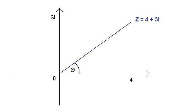
The angle between a complex number and the real axis is known as its phase ($\theta$). The magnitude and phase of a complex number can be found by trigonometry.
For a general complex number $Z = A + Bi$
Magnitude = $\sqrt{A^2 + B^2}$
Phase (also known as argument) = $\arctan(\frac{B}{A})$
We may also represent complex numbers in both polar and exponential form.
Polar: $Z = R( \cos(\theta) + i \sin(\theta))$
Exponential: $Z = Re^{i\theta}$ (Euler's formula), where $R$ is the magnitude and once again $\theta$ is the phase.
It is good practice to add and subtract complex numbers in Cartesian form whilst multiplying and dividing in exponential (or polar); this simplifies calculations greatly.
Question:
Find the result of multiplying (3 + 4i) and (1+ 2i).
Solution:
$3 + 4i =5e^{i \arctan(\frac{4}{3})}$
$1 + 2i = \sqrt{5}e^{i \arctan(2)}$
$(3 + 4i)\times (1+ 2i) = 5e^{i \arctan(\frac{4}{3})}\times \sqrt{5}e^{ i \arctan(2)} = 5\sqrt5e^{i (\arctan(\frac{4}{3})+\arctan(2))}$
This complex number therefore has a magnitude $R =5\sqrt5$
And an argument $\theta = \arctan(\frac{4}{3}) + \arctan(2) \approx 116.6$ degrees
Complex Impedance
Resistors:
We know that the impedance of a resistor is simply R, this is purely resistive; in complex form this is written as $R + 0i$.
Capacitors:
The impedance of a capacitor, $X_C$, is defined as $X_C = \frac{1}{2\pi i f C}$, where $f$ is the frequency of the alternating current, $C$ is the magnitude of the capacitance and $i =\sqrt{-1}$
We see that the impedance is frequency dependant; the impedance of a capacitor is inversely proportional to the frequency. This frequency dependence provides capacitors with a filtering ability; they effectively filter low frequency signals whilst allowing high frequency to pass. The two fundamental uses of a capacitor include coupling and bypass capacitors.
Coupling Capacitor:
Coupling capacitors are placed in series with a component, its purpose is to filter DC signals whilst allowing AC signals to pass.
Bypass Capacitor:
Bypass capacitors are connected in parallel with a component, at high frequencies they short circuit this component (the current is allowed to bypass). The bypass capacitor conducts an alternating current around a component whilst allowing DC through it, it can be used to filter electric noise caused by ripple voltages.
Inductors:
The impedance of an inductor, $Z_L$, is defined as $Z_L = 2\pi i f L$, where $L$ is the magnitude of the inductance.
The impedance of an inductor behaves in the opposite manner to the capacitor - its impedance is proportional to frequency.
Electrical Filters
The frequency dependent characteristics of inductors and capacitors enable the creation of many useful circuits, these include high pass, low pass and band pass filters.
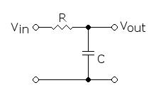
Low Pass filter:
A low pass filter is a circuit which allows easy passage of low frequency signals but prevents the passage of high frequency signals. A simple low pass filter is shown below.
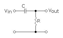
High Pass filter:
A high pass filter is a circuit which allows easy passage of high frequency signals but prevents the passage of low frequency signals. The circuit is shown below.
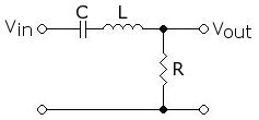
Band Pass filter:
By combining the properties of the high pass and the low pass filter we can accomplish a band pass filter. At low frequency the majority of the input will be dropped across the capacitor whilst at high frequency it will be dropped across the inductor. There exists a small range of frequencies at which an appreciable voltage will be output, this occurs when the impedance of the capacitor matches the inductor and is known as the resonant frequency.