Pinhole Camera
Problem
Equipment required
- sheet of card
- screen or large sheet of white paper
- blackout for windows
- aluminium foil, about 5cm x 5cm
- pin or sharp point
- tape
- scissors
- ruler
- candle or other light source

Making the pinhole camera
- Cut a square about 2cm x 2cm in the centre of the cardboard.
- Put the foil over the square hole and tape it to the card.
- Use the pin or point to make a small hole in the foil.
Setting up the pinhole camera
To get an image with your pinhole camera:
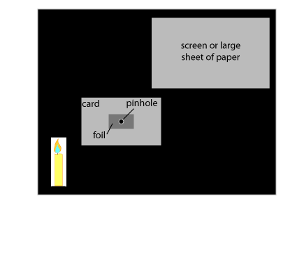
- Set it up as in the diagram and turn out all other lights.
- You should be able to see an image of the candle flame or other light source on the screen - try different positions and see what gives the best image.
Investigating your pinhole camera
- What do you notice about the image? Why do you think it is like this?
- What happens to the size of the image as you move the sheet of paper or screen further away, but with the candle staying still? You could draw a graph of image height (vertical axis) against the distance of the paper or screen from the pinhole camera (horizontal axis).
- Look at your graph - what do you think it tells you?
- For each pair of measurements, calculate the result when you divide the height of the image by the distance between the camera and the screen or paper. What do you notice? Can you explain this?
Getting Started
Then look at the triangle formed by the height of the object and the rays of light going to the pinhole and the triangle formed by the rays of light beyond the pinhole and the height of the image on the screen.
What can you say about those triangles?
Student Solutions

The candle has height h, and is a distance d from the pinhole.
The pinhole is a distance D from the screen.
The image is height H on the screen.
The red lines show the path of rays of light from the candle to the image.
You should notice that the image is upside down - can you see why?
As the length D is increased (keeping d constant) the height H should increase proportionately.
(Imagine what would happen to the rays of light if you moved the screen away from the pinhole.)
If you draw a graph of H against D it should be a straight line.
The two red triangles made by the rays of light, the candle and the screen are similar.
One of the conditions for similarity is equal angles, which are marked in the same colour.
The two green angles are the same because they are enclosed within the same straight lines (opposite angles).
The two turquoise angles are the same because the lines marked h and H are parallel, and these two angles are therefore equal (alternating angles).
The two orange angles are equal for the same reason (alternating angles).
Because the two red triangles are similar, the sides and the heights of the triangles are in proportion, so:
This can be rearranged to give:
Drawn as a graph, with H on the vertical axis and D on the horizontal axis, provided h and d are held constant, this should give a straight line through the origin, with gradient h/d.
Teachers' Resources
Why do this problem?
This problem is linked to the project Observing the Sun and the Moon, from our STEMclubs projects. Observing the Sun is interesting but potentially dangerous - no one should ever observe the Sun directly with the naked eye. One way round this is to use a pinhole camera.

The science
The principle of the pinhole camera is the principle behind all cameras. Pinhole cameras are an example of the camera obscura, which is Latin for a vaulted room (camera) which is dark (obscura). A camera obscura projects an image of its surroundings onto a screen, and is an early fore-runner
of modern photography.
The pinhole camera (and camera obscura) works by reflecting light off an object which is then focused onto a surface, creating an image of the object on the surface. Focusing would be via a lens in a modern camera, but in the pinhole camera it is the pinhole which focuses the rays of light.
The maths
In situations where we might use a camera, light rays travel in straight lines which means we can use geometrical principles to investigate what is happening in the pinhole camera.
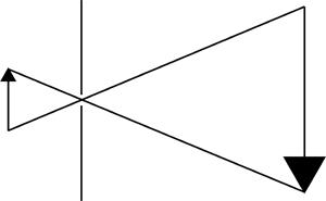
The diagram on the right illustrates how the pinhole camera works. The upright arrow represents an object. Light rays travel from the object through the pinhole and onto a surface on which the image of the arrow can be seen.
Using similar triangles, we can work out how big the image will be and we can also see why it will be upside down compared to the original object.
Possible approach
Students should be encouraged to make their own pinhole cameras, and to find out how the image appears in relation to the object by experiment. Once they have grasped that (a) the image is upside down, and (b) that its size varies depending on where the pinhole and the image surface are placed relative to the object, then data can be collected.
Experimentally, it is good practice to clarify what the variables are - for a given object, these are the distance of the object from the pinhole, the distance between the pinhole and the image surface, and the height of the image. Either the distance of the object from the pinhole or the distance of the pinhole from the image surface should be kept constant. The other distance will
then be the independent variable, with the image height the dependent variable.
Graphing the results should produce a straight line, indicating a linear relationship.
A diagram like that above will help them to understand what is going on, and how the heights of the objects and the image relate to each other.
Key questions
- Why is the image upside down?
- If I move the object relative to the pinhole and the image surface, how does the height of the image change?
- What are the variables in this experiment? Which are the independent variables, which the dependent? Why do we need to hold one of the independent variables constant?
Possible extension
Challenge students to explain with a diagram why a large hole will give a bright but fuzzy image, while a small hole will give a sharper, but less intense, image.
Possible support
Suggest students start by varying the position of the screen only, keeping everything else constant, and see what effect this has on the height of the image.
