Copyright © University of Cambridge. All rights reserved.
'Elastic Maths' printed from https://nrich.maths.org/
Show menu
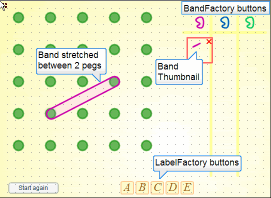
In this article I'm going to try and explain how I created the illusion that the NRICH virtual geoboard lets you stretch elastic bands between its little round green pegs. It should come as no surprise that there is a fair bit of mathematics involved in this. Whenever we want to model something in the real world inside a computer, we often end up trying to find a good mathematical model. To get the most out of reading this article, I recommend you use the geoboard to recreate the images below - at least those that can be recreated with the final version!
Stretching the model
Unfortunately, the first model that springs to mind may not be the most appropriate. In this case it is tempting to think first of Hooke's law of elasticity. This is after all a very well known mathematical model of how things like springs and elastic bands behave, giving a pretty accurate description of how the forces change as you stretch a spring. Paraphrased, it says that the force is proportional to the distance stretched.
Unfortunately, Hooke's law in this context is a very good example of a completely inappropriate mathematical model. In the virtual geoboard, you can't feel any forces through your mouse as you manipulate the rubber bands. We have to look elsewhere for a way to create our illusion..
Modelling the stretch
To get to a more useful model I needed to think about how the user would create and manipulate those rubber bands. Some of this was straightforward user interface design. I would represent a pot of rubber bands with a button. Pressing the button - I called it the 'BandFactory' in my code - would create a small relaxed band that could be dragged on top of a peg. Pressing the mouse button again over this band and dragging would stretch the band, and if I released the mouse button when I was over another peg, then the band would attach to the new peg.
I would then have something like this:
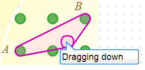
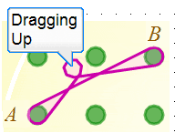
From this point it would be natural to insert my finger (really the mouse pointer) inside the rubber band, and drag it over another peg. If I dragged down a little, then I'd expect to see something like this: (The small purple circle is representing my finger here.)
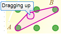
I might also drag upwards, in which case I'd expect a result like this:
Problem time
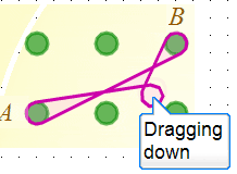
So far so good, and I haven't needed to use very much mathematics. Or have I? Well, the truth of the matter is that the first time I tested this part of the program, the result was not what I wanted. It sometimes did the right thing, but sometimes - depending on where the two original points were - I would see this:
or this:
This wasn't as surprising as it might seem partly because I never expect things to work first time and partly because I knew that I'd left a little bit of code to sort out later. I hadn't yet given the machine a good way to decide which arm of the band needed to be moved. In this case, dragging up should move the upper arm, and dragging down should move the lower arm. When the program went wrong it was choosing the wrong arm.
I'm also glossing over the coordinate geometry that was needed to draw the rubber bands going round the pegs. Suffice to say that the algorithm used to draw the rubber band going round a peg also ensured that it developed an extra loop around my finger whenever the program misbehaved and picked the wrong arm to drag.
In the internal numerical world of the machine, this problem looks different. It changes character and becomes algebraic. Let's try to recast the problem in these terms.
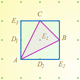
Here, $A$ is a point with coordinates $(a_0, a_1)$, and $B$ is at $(b_0,b_1)$. The program draws the elastic band by choosing some starting point a distance $r$ from the line segment $A B$. It then circumnavigates the line segment $A B$ always maintaining that fixed distance $r$ and drawing a purple line as it goes. The two arms are distinguished by direction - one is the arm drawn from $A$ to $B$, and the other goes from $B$ to $A$. A third point - my finger at $C$ - is then introduced and dragged to $(c_0, c_1)$.
We are now in a position to restate the problem. Given $A=(a_0, a_1)$, $B=(b_0,b_1)$ and the moving $C=(c_0, c_1)$, how is the machine to know whether to insert $C$ in the arm $AB$ or the arm $BA$? Assume a circumnavigation of $AB$ in the positive anticlockwise sense. The problem does not look so easy now, but it is immediately apparent that if the circumnavigation was in the opposite sense, $C$ would insert in the opposite arm.
Lifting Off
I'll leave that one with you for a bit while we look at another little problem that arises from our desire to mimic rubber band behaviour. This second problem is, "How do we get the bands off the pegs?" and it turns out to be closely related to our first problem. Look at how the situation plays out in the next few diagrams:
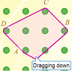
Here, I had previously made a parallelogram by wrapping the points $A$, $B$, $C$ and $D$, and I'm about to unhook the band from $A$. You can see that the band is still attached to peg $A$ since it changes direction there. If I pull down just a little further, $A$ would be wholly inside the band and unattached:
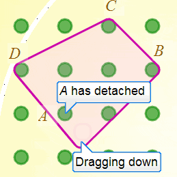
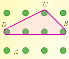
If I now let go of the mouse button to simulate removing my finger, then the band should snap to wrap around $B$, $C$ and $D$ only in a rather pleasing elasticated way. (Note to self: I really must add some sound effects!)
Aha! Things are beginning to make sense. The rubber band detaches itself from $A$ because it refuses to bend inwards to stay attached. If we constrain the rubber bands so they always make convex shapes we have a natural way to mimic in 2D the 3D act of lifting a band off a peg.
This is a really helpful observation because I know that this problem has been solved before. It's the problem of finding the smallest convex hull that encloses a set of points. I type 'convex hull' into Google, and find everything I need to know on the 'Incremental Convex Hull Algorithm ' - courtesy of an excellent Australian web site. There is a bonus in the shape of one component of this algorithm known as the 'can see test'.
The 'can see test'
The core of the incremental convex hull algorithm is a small test needed to determine whether the points of a triangle are labelled in a positive anticlockwise sense, or a negative clockwise sense. I hope this is beginning to sound familiar to you - and yes - it will also provide the solution to our earlier problem. The web page suggests that we need to worry about calculating the area of the triangle and see whether it comes out positive or negative. This might seem like a strange idea - that areas can be negative - but it arises quite naturally if we attempt to calculate areas using coordinate geometry.
The test is known as the 'can see' test because one imagines that only one side of each line is visible to another point. The test determines whether a line presents its visible aspect to the point.
Coordinated Areas
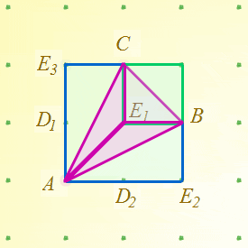
Let's go back to our orginal problem involving the fixed points $A$ and $B$, and the movable point $C$ and try to calculate the area of the triangle $A B C$. The virtual geoboard itself is quite a useful tool in doing this. (I knew there was a reason to go through all this!)
The machine only knows about coordinates, so it's quite useful to surround the triangle with the smallest enclosing rectangle with sides parallel to the axes. On the geoboard it looks like this (I've clicked on one of the vacant green pegs to minimise their sizes):
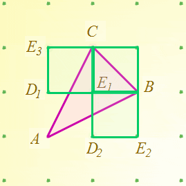
I said 'rectangle' because in general the bounding box of a triangle will be rectangular rather than square. I'll continue to use the term 'rectangle' in the text as this is the general case even though in my diagrams above and below many of the rectangles I am talking about happen to be square.
Let's add a few more bands to help calculate areas:
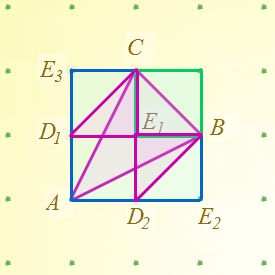
Notice that triangle $B C E_1$ is half of the green rectangle, triangle $C E_3 D_1$ is half of rectangle $C E_3 D_1 E_1$, and triangle $B E_1 D_2$ is half of rectangle $B E_1 D_2 E_2$. Furthermore, we can transform the two triangles $B E_1 D_2$ and $C D_1 E_1$ to areas inside $A B C$ by moving $D_1$ and $D_2$ in area preserving sheers
and so demonstrate that the area of triangle $A B C$ is one half the sum of the areas of the 3 green bands below. $A$ is the special point of the triangle because it is the one point that coincides with a corner of the triangle's bounding box. There must always be at least one such point.
The area can now be calculated easily in terms of the coordinates $a_0, a_1, b_0, b_1, c_0, c_1$. I won't spoil the fun by doing this for you, but you should be able to verify that the resulting expression is either positive or negative depending on whether $A$, $B$, and $C$ cycle in the positive or negative sense. When the area is zero, the points $A$, $B$ and $C$ are colinear, and of course in that situation we don't need to decide between moving $AB$ or $BA$ since we move neither.
Is this model good enough?
Putting everything together, we now have a model that can draw and manipulate convex polygons. Should we go further, and implement concave polygons too? It is after all possible to create a concave polygon on a real geoboard by lifting the band over selected pegs.
Could we do this and still use the convex hull technique? Yes - I think we could. Things would get a little more complicated. The program would have to record whether pegs used in a polygon were attached on the inside or on the outside, and I would have to modify the drawing alogorithm so it weaved in and out as needed. I would also need to be able to select a band to manipulate so my 'finger' could start on the outside and 'know' which band to lift over pegs. This is all possible, but begins to violate the engineers 'KISS = Keep It Simple, Stupid' maxim. So I'm reluctant to allow concave polygons on these pragmatic grounds.
Fortunately, there's a much stronger reason for rejecting concave polygons - and it's a mathematical one. Convex shapes created with rubber bands have the very useful property that the angles between the straight line segments are invariant when we change the peg size. Angle invariance is violated by concave polygons. Since one of the main purposes of using the geoboard is to investigate angles, this is a property we cannot afford to lose. Our virtual geoboard is in fact better than the real one because it excludes the possibility of creating a concave polygon with a single rubber band.
Concave polygons can still be created with the virtual geoboard. You simply have to use more than one rubber band to make them. You could, for example, use one band for each line segment. Angles would still be preserved when peg sizes change.
Stand back and admire
We men are prone to this. I'm sure you've seen us do a job and then stand back and admire it for half an hour. I have to admit that this was one of those jobs for me. I find it strangely beautiful that a rather obscure algorithm is responsible for something so tactile as making it feel like you are manipulating a stretchy rubber band when you are actually just clicking and dragging a mouse. Hope you feel the same too!
Mike